


In the automotive industry corrosion protected galvanized advanced high strength steels with high ductility (AHSS-HD) gain importance due to their good formability and their lightweight potential.
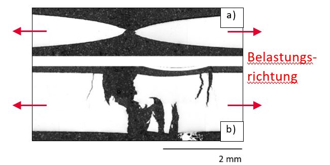
Unfortunately, under specific thermomechanical loading conditions such as during resistance spot welding (RSW) galvanized AHSS-HD sheets tend to show liquid metal embrittlement (LME). LME is an intergranular decohesion phenomenon leading to remarkable loss of ductility (Fig.1). The occurrence of LME depends for a given zinc galvanized material mainly on temperature, tensile stresses and plastic deformation. These influences were investigated for a dual phase steel with an ultimate tensile strength of 1200 MPa and high ductility (DP1200HD) by means of systematic isothermal hot tensile testing on a Gleeble® 3800 thermomechanical simulator. In addition, theoretical ab-initio based investigations on the grain boundary cohesion in the material system Fe-Si-Al-Zn revealed the influence of chemical composition. Based on the experimental findings a machine learning procedure using symbolic regression was applied to calibrate an LME damage model that accounts for the governing quantities temperature, plastic strain and strain rate.
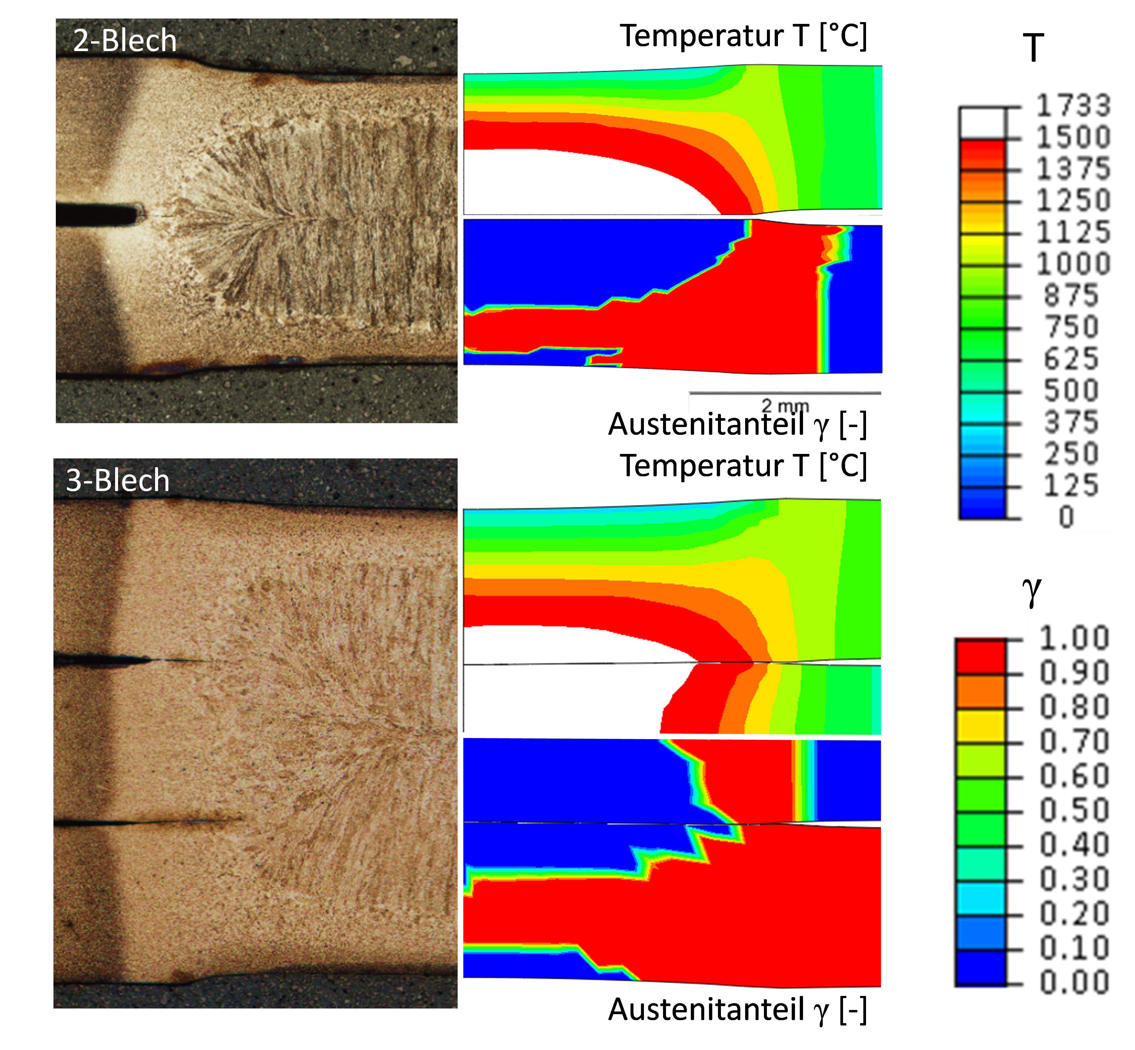
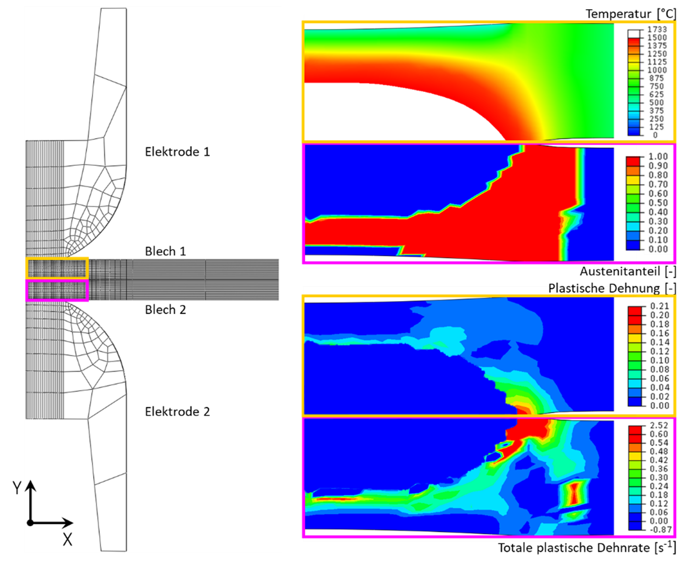
These quantities are in turn calculated by means of a multi-physical finite element (FE) model of the resistance spot welding process. The model covers the evolution of the electrical, thermal, mechanical and metallurgical fields during the complete spot welding process. Phase transformations in the base material to austenite and further on to steel melt during heating and all relevant transformations while cooling are considered (Fig.2).
The model is fully parametrized based on lab scale material testing, accompanying model-based parameter determination and literature data, and it is validated by a large number (>300) of optically examined micrographs of weld spots that have been subjected to burst tests.
Impact and effect
Commonly, trial-and-error tests are carried out to determine optimum welding conditions to achieve high spot weld quality and to reduce LME. The developed integrated simulation of the material, process and the weld avoids this extensive testing and reveals computer-aided strategies to reduce Liquid Metal Embrittlement (LME).
One strategy is the new electrode geometry developed within the project, a second strategy is a novel electrode material concept using TiN-TiB2 or TiN coated molybdenum, a third strategy is the down-ramping of the current (see Fig.3) and a fourth strategy is increasing the holding time after welding. The positive effect of all four strategies could be verified experimentally in laboratory welding tests.
Moreover, the process simulation results, namely the residual stress state, the local microstructure condition, the weld geometry and the damage condition are important starting conditions for a detailed simulation of the performance of the spot weld itself and the weld structure as a whole.
Project coordination (Story)
Dr. Werner Ecker
Key Researcher
Department Simulation
+43 3842 45922 - 26
werner.ecker(at)mcl.at
Project partners
voestalpine Stahl GmbH, Austria
Plansee SE, Austria
Daimler AG, Germany
Montanuniversität Leoben, Austria